Principles of PEM Operation
PEM PRINCIPLES OF OPERATION
View an Animated Tutorial of PEM Principles of Operation.
The phenomenon of photoelasticity is the basis of operation for the PEM. If a sample of transparent solid material is stressed by compression or stretching, the material becomes birefringent, that is, different linear polarizations of light have slightly different speeds of light when passing through the material.
PEM Series I modulators use a rectangular shape for the modulator optical element. In the Model I/FS50, a fused silica bar is made to vibrate with a natural resonant frequency of about 50 kHz. This vibration is sustained by a quartz piezoelectric transducer attached to the end of the bar.
At the center of the optical element an oscillating birefringence occurs at a frequency of about 50 kHz. The magnitude of the birefringence is controlled electronically by the PEM Controller.
RETARDATION EFFECTS OF COMPRESSION AND EXTENSION –
The effect of the modulator on a linear polarized monochromatic light wave is shown in slide 3 of the Polarization Primer. The plane of polarization is at 45° to the modulator axis before passing through the modulator. If the optical element is relaxed the light passes through with the polarization unchanged.
If the optical element is compressed, the polarization component parallel to the modulator axis travels slightly faster than the vertical component. The horizontal component then “leads” the vertical component after light passes through the modulator. If the optical element is stretched, the horizontal component “lags” behind the vertical component.
The phase difference between the components at any instant of time is called the retardation or retardance. The peak retardation is the amplitude of the sinusoidal retardation as a function of time.
The retardation (in length units) is given by
A(t)=z[nx(t)-ny(t)]
where z is the thickness of the optical element and nx(t) and ny(t) are the instantaneous values of refractive index along the x and y directions. Common units for retardation include distance (nanometers, microns), waves (quarter-wave, half-wave), and phase angle (radians, degrees) The PEM-100 Controller can display retardation in waves or phase angle.
QUARTER-WAVE RETARDATION –
An important condition occurs when the peak retardation reaches exactly one-fourth of the wavelength of light. When this happens, the PEM acts as a quarter-wave plate. Figure 1 shows this condition at the instant retardation is at its maximum.

The polarization vector traces a right-handed spiral about the optic axis. Such light is called “right circularly polarized.” For an entire modulator cycle, Figure 1 shows the retardation vs. time and the polarization states at several points in time. The polarization oscillates between right circular and left circular, with linear (and elliptical) polarization states in between. Please see slide 4 of the Polarization Primer.
HALF-WAVE RETARDATION –
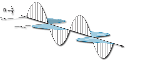
Another important condition occurs when the peak retardation reaches one-half of the wavelength of the light. When this happens, the PEM acts as a half-wave plate at the instant of maximum retardation and rotates the plane of polarization by 90°.

At maximum retardation, the polarization states are linear, rotated by 90°. The half-wave retardation condition is particularly important for calibration of the PEM. This can be seen in slide 5 of the Polarization Primer.
SYMMETRIC OPTICAL ELEMENT –
PEM Series II modulators use a unique symmetric or “octagonal” shape for the modulator optical element, see figure 3. This utilizes a “two-dimensional” standing wave which approximately doubles the retardation available with a given drive voltage. Series II modulators are particularly useful in the infrared spectrum.
